孔系加工立式組合加工機床設計
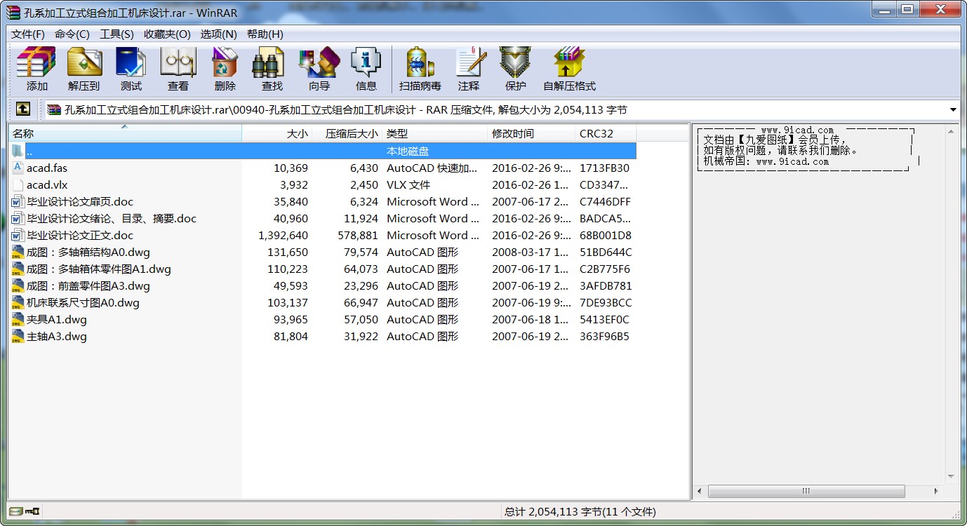
- 文件介紹:
- 該文件為 rar 格式(源文件可編輯),下載需要
20 積分
-

- 孔系加工立式組合加工機床設計.rar
緒 論
組合機床是以通用部件為基礎,配以少量專用部件,對一種或若干種工件按預先確定的工序進行加工的機床。它能夠對工件進行多刀、多軸、多面、多工位同時加工。在組合機床上可以完成鉆孔、擴孔、鉸孔、鏜孔、攻絲、車削、銑削、磨削、及滾壓等工序,隨著組合機床技術的發慌,它能完成的工序的范圍日益擴大。在組合機床自動線上可以完成一些非切削工序,例如:打印、清洗、熱處理、簡單的裝配、試驗和在線自動檢查等工序。
組合機床及其自動線所使用的通用部件是具有特定功能,按標準化、系列化、通用化原則設計、制造的組合機床基礎部件。每種通用部件有合理的規格尺寸系列,有適用的技術參數和完善的配套關系。組合機床設計應根據機床性能要求配套液壓、氣壓和電控等系統。
許多大型、形狀復雜的工件,需要的加工工序很多,不可能在一臺組合機床上全部加工完成,這就需要用多臺組合機床加工,按工件加工順序依次排列,組成組合機床流水線,在組合機床流水線的基礎上,發展成組合機床自動線。
組合機床與通用機床、其它專用機床比較,具有以下特點:
(1) 組合機床上的通用部件和標準零件約占全部機床零、部件問題的70%——80%,因此設計和制造周期短,經濟效益好。
(2) 由于組合機床采用多刀加工,機床自動化程度高,因而比通用機床生產效率高,產品質量穩定,勞動強度低。
(3) 組合機床的通用部件是經過周密設計和長期生產實踐考驗的,又有專門廠家成批生產,它與一般專用機床比較,其結構穩定,工作可靠,使用和維修方便。
(4) 組合機床加工工件,由于采用專用夾具、組合夾具和導向裝置等,產品加工質量靠工藝裝備保證,對操作工人的技術水平要求不高。
(5) 當機床被加工的產品更新時,專用機床的大部分部件要報廢。組合機床的通用部件是根據國家標準設計的,并等效于國際標準,因此其通用部件可以重復使用不必另行設計和制造。
(6) 組合機床易于聯成組合機床自動線,以適應大規模和自動化生產需求。
目前,我國組合機床已廣泛應用到大批、大量生產的行業,例如:汽車、拖拉機、柴油機、電動機和縫紉機等。
摘 要
(一)電機機座鉆孔組合機床是大型組合機床,它的配置型式具有固定式液壓夾緊的單工位組合機床,這類組合機床夾具和工作臺都是固定不動的,動力滑臺實現進給運動。滑臺上的動力箱實現切削運動,根據工件結構特點,以及精確要求,采用結合面為定值基準面。 在基準面對應的另一圓柱面上,用壓塊壓緊,由于結合面的加工精度較高,以它為基面,完全可以達到要求的加工精度。
(二)幾何機床總體設計----三圖一卡①“被加工零件工序圖”它是組合機床的設計的主要依據,它是制造使用,檢修和調整機床的重要技術條件②繪制加工示意圖,它是刀具夾具,多軸箱,液壓電器裝置設計及通用部件選擇主要原始資料,它是調整機床,刀具及試車依據。③繪制聯系和運動關系及檢驗機床各部件相對于位置及聯系是否滿足加工要求,通用部件的選擇是否合適,并為進一步開展主軸箱,夾具等專用部件,零件的設計提供依據。④相對生產率計算卡,它用來反映機床的加工過程,完成這一動作所需要的時間,切削用量,機床生產率及機床負荷率。
(三)組合機床主軸箱設計,按專用要求進行設計,由通用零件組成,其主要作用是根據被加工零件的要求,安排各主軸位置并將動力和運動由電機或動力部件傳給各主軸,使之得到要求的轉速,機床主軸箱選用400*400,用中間傳動軸帶動主軸傳動。
(四)夾具設計
在前述定位基準面選擇的前提下,用擺動式壓板杠桿夾緊結構,夾緊力經驗算可以保證。
關鍵字:
組合機床 ;動力滑臺 ;動力箱 ;主軸箱 ;夾具 ;
Abstract
(一)Combmtvin drilling machine is a large combination machine it adept a dispose form. The form has a fixed fitture’s single working location combination.
This kind of combination machine fitture and working bench are all fixed. Powen-sliding plat makes advam cry mourent. The power box on the power sliding plat from made scatting movement.This comgination and agle in instuit and is comvenient in desxging making and operating .Acording to precision demerd it adopt a datum place fixed in side .It is lined light with après lump on the other lylinder side against the datum palne .Itcan read working prelistion indemard a wording to the datum plane. Bacause of it is high working precision in side besides it has a round hole in high precision in side. It has a threaceling hole on the ohassion.
It can make full use of the strulture charactlst of the work piece. To design two short round cancel in the round hole in the side. To limit three degrees .To design acutside cancel on the bassface the battom. To limit one free degree. To limit three free degree one the deofimtine datum plane.It definet up a ccnrately and it’s fixture power is depene.
(二)To desing the combination machine body-therr draning and one carcl that is ① the working orther draning of the working spares . it’s the major basis of the combination maching body. It’s a important paper in making using excmining and rensing maching .②To draw working schematw. Drawing it’s for design a cutting tool. Assist tool afixture a multiple axle box hydravlive,pressure and a deetric capacity derise and important first hand date of the natirrad. Pants chovced and it’s a rewse machine kinf tool and the mgor basis for the test run.③ To draw the relation dimension drawing the relation dimension drawing is to impress the matual .assembly nelation and the motin redation of the each form spanes of the machine.in order to enamine the relative .Pustion of all the machine spares and if the dimersion nelational .Spares is fix ,in the disigerents of dere loping the main axle box fixtrer’s special purpose pats.④Todesign the machin productirilg planning card .It’swod to report the working process of the machine to finish the need tine the cutting capacity the machine producticity and machine’s rate for the cach activity.
(三)To design the comuination machine main axle box .To design it a cocording to the special cemoncl.It’s made up of the mational pants.As magin use is to arrange the position of all the mational axle box and transrnit the power and the motion to all the main axle by the electrical machinery or the power pants .According to the working demands of the worked pants and make it taget the demand transpont speed.The machine main axle is mode in side 400*400. It’sdraved by the mediwm drive.
(四)To desing the fixture
First to choice the forer word fixed position datum plane.It’s fixed by swing depressor fixtume structure the despower can be assured by checking computations.
Kdyword:
The combination machine ;Powen-sliding plat ;The power box ;The main axle box ;The fixture
目 錄
1 組合機床總體設計…………………………………………………………1
1.1 組合機床方案…………………………………………………………1
1.1.1 組合機床的制定方案制定的主要因素…………………………1
1.1.2 分析被加工工件…………………………………………………3
1.1.3 制定本設計的機床方案…………………………………………3
1.2 確定切削用量及選擇刀具……………………………………………3 1.2.1 根據工件的材料及加工孔直徑確定切削用量…………………3
1.2.2 確定切削力、切削轉矩、切削功率及刀具耐用度……………3
1.2.3 刀具的選擇………………………………………………………7
1.3 初步確定主軸及傳動軸直徑…………………………………………7
1.4 三圖一卡………………………………………………………………8
1.4.1 被加工零件工序圖………………………………………………8
1.4.2 加工示意圖………………………………………………………8
1.4.3 機床聯系尺寸圖…………………………………………………14
1.4.4 組合機床生產率計算卡…………………………………………15
2 多軸箱的設計 ……………………………………………………………20
2.1 多軸箱材料的選擇……………………………………………………20
2.2 多軸箱輪廓尺寸的確定………………………………………………20
2.3 軸類零件的選用………………………………………………………20
2.3.1 鉆削類主軸………………………………………………………20
2.3.2 傳動軸……………………………………………………………21
2.3.3 軸的材料…………………………………………………………21
2.4 齒輪型式的選擇………………………………………………………21
2.5 設計計算………………………………………………………………21
2.5.1 繪制多軸箱設計原始依據圖……………………………………21
2.5.2 主軸結構型式的選擇……………………………………………22
2.5.3 傳動系統的設計計算……………………………………………22
2.5.4 多軸箱結構設計…………………………………………………32
2.5.5 主軸的設計………………………………………………………34
2.5.6 手柄軸的設計……………………………………………………40
2.5.7傳動軸的設計 ……………………………………………………42
2.5.8 葉片泵軸的設計 …………………………………………………44
2.5.9 動力箱輸出軸的設計 ……………………………………………45
2.6 軸的校核 ………………………………………………………………46
2.6.1 求各軸的功率及轉矩 ……………………………………………46
2.6.2 主軸的校核 ………………………………………………………47
2.6.3 手柄軸的校核 ……………………………………………………48
2.7 軸承的校核 …………………………………………………………52
2.7.1 主軸上推力球軸承的校核 ………………………………………52
2.7.2 主軸上深溝球軸承的校核 ………………………………………52
3 夾具的設計…………………………………………………………………53
3.1 機床夾具介紹 …………………………………………………………53
3.1.1 夾具的分類 ………………………………………………………53
3.1.2 專用夾具的組成 …………………………………………………53
3.2 夾具的設計……………………………………………………………54
3.2.1 定位裝置的設計 …………………………………………………54
3.2.2 夾緊裝置的設計 …………………………………………………55
3.2.3 夾緊方案的制定 …………………………………………………55
3.3.4 夾具圖 ……………………………………………………………56
結 論 …………………………………………………………………………57
參考文獻 ………………………………………………………………………58
致 謝 …………………………………………………………………………59
附錄 1 …………………………………………………………………………60
附錄 2 …………………………………………………………………………61
...
文檔留言 共有條評論

 熱門關鍵詞:


 豫公網安備 41072402000322號

